
This install was a beast, but I finally got it done. This picture doesn’t show the audio lines attached to the nesrgb board, the expansion line connected, or Ace’s modifications (explained below) but it is the most complete shot I have.
The Plan
- Install NESRGB.
- Install Borti’s NESRGB-IGR board and connect to the NESRGB.
- Connect expansion audio for the Everdrive N8 using FirebrandX’s Guide.
- Modify the NESRGB audio circuit to be better, according to Ace’s (of the sega16 forums) specifications.
NESRGB Install
This went about as well as I expected it to. I don’t have a desoldering station yet, so removing the PPU was very challenging. I finally got it out with a combination of adding fresh solder, using wick, and applying a solder sucker, along with lots of flux. I accidentally lifted a pad off of the bottom but this was easily fixed with some kynar once the socket was soldered in.
After the PPU was out, all I had to do was solder in the socket, solder the PPU to the NESRGB board, and pop it in. I then connected the audio lines and set the jumpers for NTSC and TTL level sync. I also set the jumper to use the NES’s stock voltage regulator, which in this case meant using the one on Borti’s board that replaces the stock power circuit. Next I connected Bort’s board.
NESRGB-IGR
This handy board replaces the RF box and has a new power circuit, along with composite video and mono audio out, and a nintendo multiout in place of the RF out and switch. Only a little bit of plastic needs to be cut for it to fit in nicely:

The board was then connected to the NESRGB using some multicore shielded cable. The guide on the Github Repo says this is necessary to avoid noise. These connections for RGBS, CVBS, S-Video, audio, and 5V all connected to the multiout, meaning you can use any cables for Super Nintendo, N64, etc. and they will work. Borti’s board also connects to the palette switch of the NESRGB board, meaning you can change palettes using the reset button or a button combination on the controller; the same is true with in game reset, though this can be a bit finicky.
Expansion Audio
I followed FirebrandX’s guide, which has lots of nice pictures, making it very easy. There is some debate over which resistor values to use, but his choices seemed fine. He also has a step by step guide on how to update the NESRGB firmware for different palettes using an Altera USB Blaster, so I highly recommend using this, especially if you don’t have experience with programming chips.
Audio Circuit
I asked Ace for some help improving the NESRGB audio circuit, and he sent me this diagram:
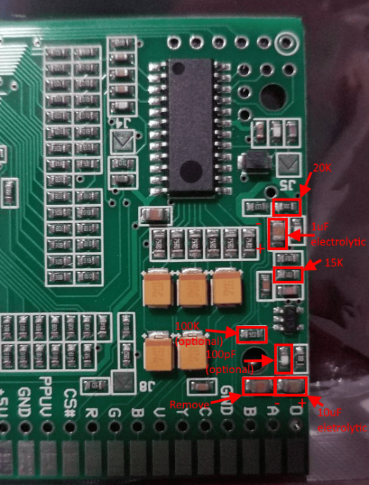
Ace said there are other ways to improve the stock audio circuit for most people rather than use the NESRGB circuit, but in this insall the NESRGB-IGR board removed the RF box which had part of the stock audio circuit on it.
The “optional” replacements here raise the gain to be in line with the AV Famicom, so I replaced them. The electrolytic caps can be tricky since the pads are fragile and there’s not much room vertically, if I were to do this again I might try to find some low profile SMD electrolytics.

There are also a few parts from the stock audio circuit that should be removed to avoid interference, as well as grounding pin 11 of the 74HCU04:
R6, C23, C21, C20 (the 0 of the silkscreen label for this cap was scratched off to expose the ground plane and shorted to pin11)

C4, FC1 removed
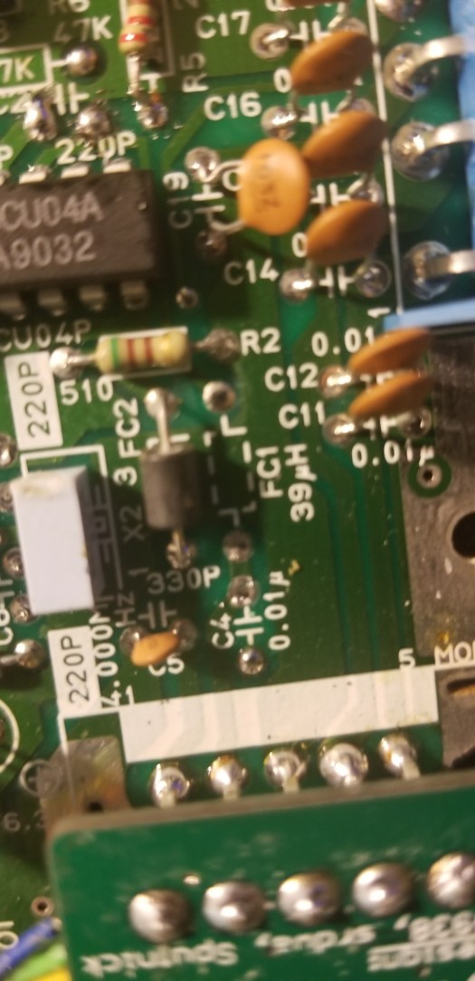
R7, R8, R9 removed.

Audio can sometimes be very subjective, but I can say that after these modifications I am impressed. The audio sounds really great and I would say it’s worth it.
After this I put it all back together and voila:

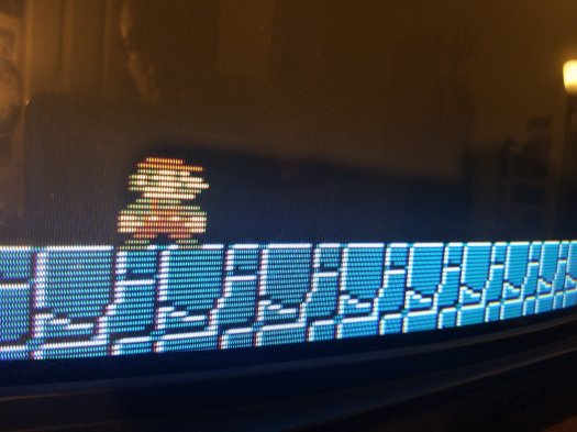
Video of it in action, showing off the palette swapping:
This mod was a success, but the NESRGB-IGR certainly complicated things. Removing the RF box required a lot of heat; my solder sucker clogged quite a bit. You need to be very careful; I found success by adding a lot of leaded solder and then using a lot of wick and the solder sucker to get the solder up. I also just pushed most of the solder away from the connections to the board rather than try to remove all of it. I’d like to try another install without the IGR board, maybe on an AV famicom or toploader NES. If you are interested, hit me up with the contact form. I’m not quite sure where I land on pricing for this yet, but for a non-IGR install I think $75 sounds good.
Happy RGB-ing.
Special thanks to:
